


Load Monitor N500

the load sensor is used to 2, or 4 channel.
Three-digit digital display and bar display on the analog indicator.
Feature
・Preventing from over loading, makes the press and the die last longer.
(Die ・Protection)
・To shorten the time of setup.(Improve Operator efficiency)
・Reduce molding defects. (Produce Quality Parts)
・Four measurement modes available.
・Simultaneous bargraph and digital display provides easy reading
・High and low level quality windows are easy to set with reading.
・Special cable eliminates any noise to set with a fine tuning knob.
・Wave form analysis may be taken by using recorder output.
・Enable to check Wave Form Analysis by TT graph software.
・Tonnage may be detected below 400spm or up to 3000spm by using a probe cam.
Outline
The monitor is a two-channel device. This means that the load from two sensors may be individually displayed. Each channel has a three-digit display for showing the load in tons. The display may also show the total load, the load difference between the two channels, the press speed in strokes per minute, the total cycle count, and the setpoint values (high, low, and target).
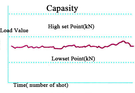
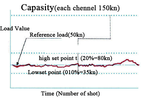
Each channel also has a bargraph display that shows the relative load in analog fashion. The bargraph shows load by percent. The operator can tell at a glance where the machine is operating.
In addition, each channel has a separate high and low setpoint control. This allows setting individual limits for each channel. Each control can be adjusted from 0 to 150%.
One of four different operating modes for using the setpoints may be selected:
1. Standard dual high and low setpoints based on the machine rating
2. Repeatability settings based on each stroke
3. AutoSet high and low based on the machine rating
4. AutoSet high and low based on the target (benchmark)
Each operating mode has a different display and will be discussed later. It is intended that the operating mode will be selected once depending on the application.
The unit may be triggered by signals crossing a threshold. The threshold setting may vary from 4-36%. A CAM or limit switch may also be used to trigger the unit. Presses less than 400 SPM may use the threshold, but higher speeds require the use of a cam switch to trigger the instrument.
Seven LEDs located centrally between the channels indicate the information being displayed in the digits. The operator may sequence through the different display data by pressing the CHANGE DISPLAY button. Each time the button is pressed the lighted LED will change to indicate the new values being shown. If no LED is lit, the display is showing the normal load.
When an out of tolerance load occurs, the shutdown relay opens and the display will indicate the fault which tripped the alarm. The relay may be engaged again by pressing the RESET push button. To prevent the relay from stopping the press, the BYPASS toggle switch may be flipped to the down position. The press will continue to run even if the monitor alarms.
The "learn" switch is an alternate-action push button switch. When the switch is pressed, the monitor is in "set-up" mode. Alarms will not shut down the press. The "target" LED will flash to indicate that a new target will be formed when the switch is released. When
AutoSet is used, releasing this switch will establish a new target, using the last load displayed. This automatically recalculates the high and low setpoint values.
Four operation modes


Specification
| BSpecification N500 ] | |
| Power Requirement | 90-130 VAC 50-60 Hz. |
| Sensor inputs | 1-4 350-ohm Wheatstone bridge strain sensors |
| Sensor ExcitationN | 10VDC at 125 ma maximum |
| Sensitivity | .028mV/V to .313mV/V high gain range at capacity 0.284mV/V to 2.50mV/V low gain range |
| Calibration Shunt | 2 Meg .1% precision shunt |
| Relay output | 1 form c contact, 10 amp rating at 120VAC○ |
| Cam input | accepts NPN or PNP proximity device○ (Supplies 12VDC @ 45ma. MAX) A limit switch may be used also |
| Speed:. | 0-400 SPM using threshold to trigger, From 400 to 2000 SPM using cam input to trigger○ |
| Computer Interface | RS485 multi-drop interface TTGraph |
| Display | 100~9900 kN(toatal) 100~650kN(Left right) |
| Operation temperture | :0 ~ 70℃ |
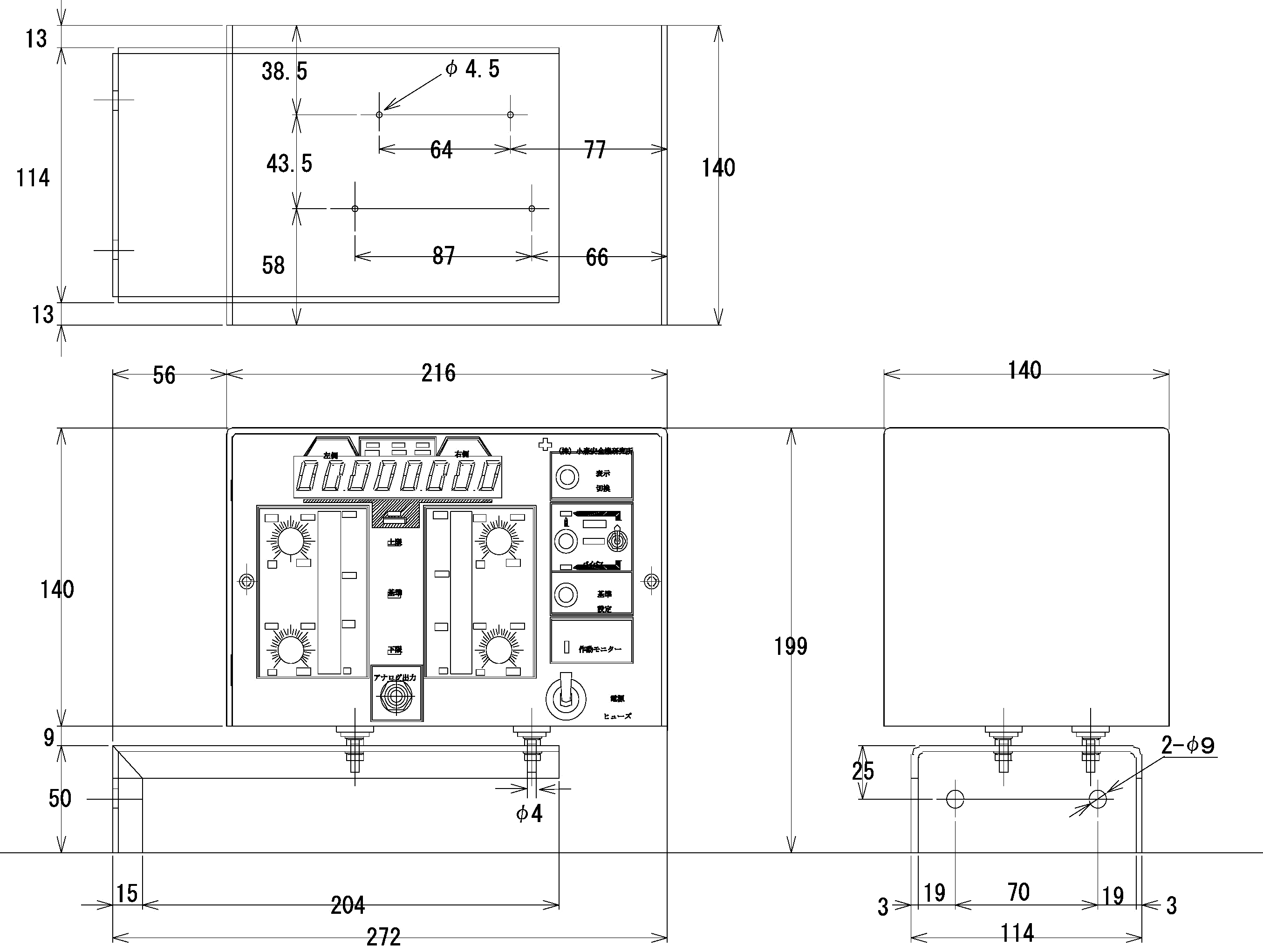
| Dimention | 247(w)× 210(h)×140(d) |
Dimention
▼Products Line
SafetyDevices AreaSensor
DSP-J
Laser Safety Device for PressBrake
Admiral AX
Light Curtain Safety Device
EOS series
LB100
Laser Safety Device
for Press Brake
Pull-out
Safety Device
Press Accesory
KBM-4
Brake Stop Timer
Scrap Shooter
SM series
Profence/safety Fence
Brock Guard/ Alminum Fence
Safety Hand Tool
Safety Press Switch
Parts for Pull out
safety device
LoadMonitor
LoadMonitor
N800
LoadMonitor
N500
LoadMonitor
N700
LoadMonitor
TTLM
LoadCell・AutoCell
LoadSensor
T400
Softwear
for Load Monitor
LoadMonitor
Comparison
Movie