


LoadMonitor N700
The N700 is important for press operation and in-die applications. It is used with "in-line" load cells and strain gages. Die setup, SPC work and quality assurance are made easier when using a N700 Tonnage Monitor. Not only will it monitor force, but it will assist in protecting your investments by reducing downtime, improving productivity and improving product quality. 。
Outline

· The press forming load function will be greatly improved at 1,2 ch.
・ Stable quality control is possible with the auto zero function even with the old press machine.
· Four load setting modes that can be used according to work.
· Compatible with TT graph software It is possible to display waveform on PC.
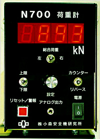
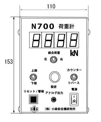
Easy operation with easy-to-read digital display
N 701 installs one load sensor and displays only the total comprehensive load and monitors loads only by total load.
N702 installes two load sensors and displays the total load, the right load, the left load which are switched with the snap switch.
The upper and lower limit loads for detecting defects can be easily set by simply turning the knob.
With automatic zero balance function that can respond to sensor temperature change and wide gain (sensitivity) adjustment function,N702 display load signal stably from small distortion to large distortion.
The measurement mode is commonly used in basic peak mode.
Because it is a compact housing, it can also be embedded inside the control panel.
selectable 4 operation mode
The N700 supports four diff erent means of setting high and low load set points:
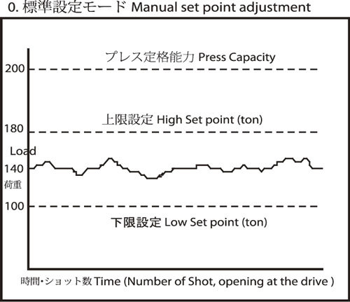
1.Manual mode
Manual set point adjustment mode monitor voluntary Load value.(manual setting to higset point and Low set point).
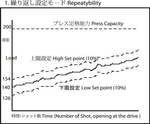
2.Repeatability mode
the set points are re-calculated each cycle based on a percentage above and below the last load value.(It can be used to monitor variations in bottom dead center accuracy of high speed press.)
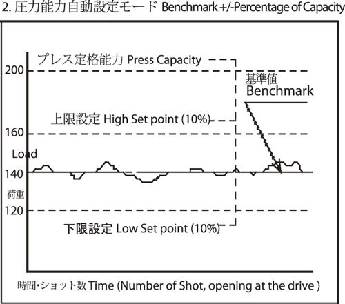
3.Benchmark +/- percentage of capacity (Auto set capasity mode)
The set points are recalculated by adding or subtracting a percentage of the machine capacity to/from the benchmark value when the benchmark is established.
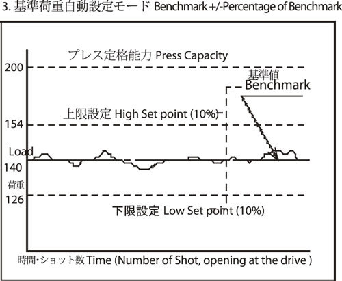
4.Benchmark +/- percentage of benchmark( Auto set target mode)
Specification
| SENSOR INPUTS | Accepts one or two 350 ohm full-bridge strain gage sensor(s). |
| SENSOR EXCITATION | +5VDC and-5VDC(10V) at70mA maximum. Short and open circuit protected. |
| ANALOG SIGNAL OUTPUT |
3.5mm stereo phone jack. 0-2.5VDC=Maximum capacity of display. |
| SENSITIVITY | 0.057mV/V to 0.625mV/V for (X10) high gain range at capacity. 0.568mV/V to 5.00mV/V for (X1) low gain rangeat capacity. |
| AUTOMATIC ZERO BALANCE | Automatic circuits maintain true zero during periods between measurements. This assures sensor and instrument accuracy regardless of ambient temperature excursions. |
| MANUAL ZERO BALANCE | +/-1mV/VSPAN RANGES : Low range(X1) provides a contiwuously variable gain range from 40 to 440. High range(X10) is continuously variable from 400 to 4400. |
| FREQUENCY RESPONSE | Flat to 1kHz. |
| SPEED | 0-400 SPM using threshold to trigger. 0-2000 SPM using cam input to trigger. |
| DISPLAY | Large4-digit display for displaying TOTAL measurement. |
| COMPUTER INTERFACE | RS485 multidrop interface. (OPTION) |
| CAM INPUT | Accepts 10 to 30VDC NPN or PNP proximity device. Supply current at 50mA maximum. Limit switch may also be used. |
| RELAY OUTPUT | 1 from c contact, 10 AMP rating at 120VAC. Bypass switch is also available for the stop circuit. |
| SECURITY | Security key jumper provides protection to the monitor settings from being changed by unauthorized person. |
| POWER REQUIREMENTS | 20WATTS. 85to 140 VAC at 50/60 Hz 170 to 280 VAC at50/60 Hz. |
| OPERATING TEMPERATURE | 0℃ to 70℃ |
| INSTRUMENT WEIGHT | Approximately 4Kg |
Dimention
▼Products Line
SafetyDevices AreaSensor
DSP-J
Laser Safety Device for PressBrake
Admiral AX
Light Curtain Safety Device
EOS series
LB100
Laser Safety Device
for Press Brake
Pull-out
Safety Device
Press Accesory
KBM-4
Brake Stop Timer
Scrap Shooter
SM series
Profence/safety Fence
Brock Guard/ Alminum Fence
Safety Hand Tool
Safety Press Switch
Parts for Pull out
safety device
LoadMonitor
LoadMonitor
N800
LoadMonitor
N500
LoadMonitor
N700
LoadMonitor
TTLM
LoadCell・AutoCell
LoadSensor
T400
Softwear
for Load Monitor
LoadMonitor
Comparison
Movie